Stock Code
301528

Driven by rising demand for rotor shafts in the electromechanical industry, higher safety requirements have been imposed on their service performance. Rotor shafts withstand driving torque and large electromagnetic torque from sudden generator outlet short circuits. To prevent personal injury and property loss induced by internal defects, this paper proposes a phased array inspection scheme for rotor shaft core defects to guarantee stable operation and equipment safety.
As shown in Figure 1-1, the rotor shaft has a complex profile consisting of cylindrical segments of varying lengths and diameters at both ends and an annular groove in the middle, posing challenges to ultrasonic inspection. Ultrasonic waves produce fixed echoes at groove edges and opposite end faces. The CAD model is imported into the Phascan device for acoustic beam field simulation to effectively analyze such fixed echoes. Probes are selected based on the workpiece profile, and matched with AOD curved wedges to achieve close surface fitting and optimized inspection performance.
1. Information on the Workpiece to Be Inspected
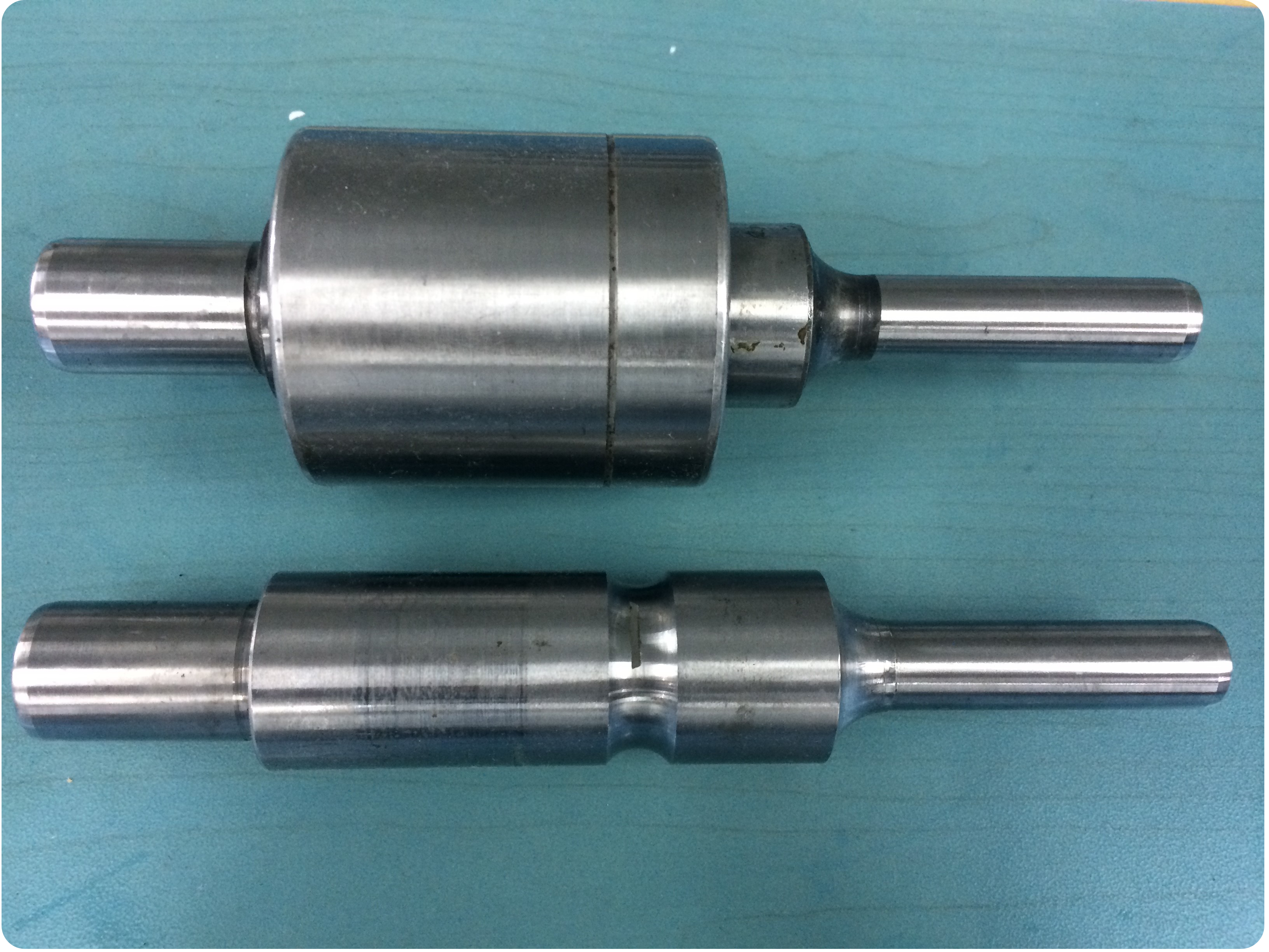
Figure 1-1 Photo of the rotor shaft specimen
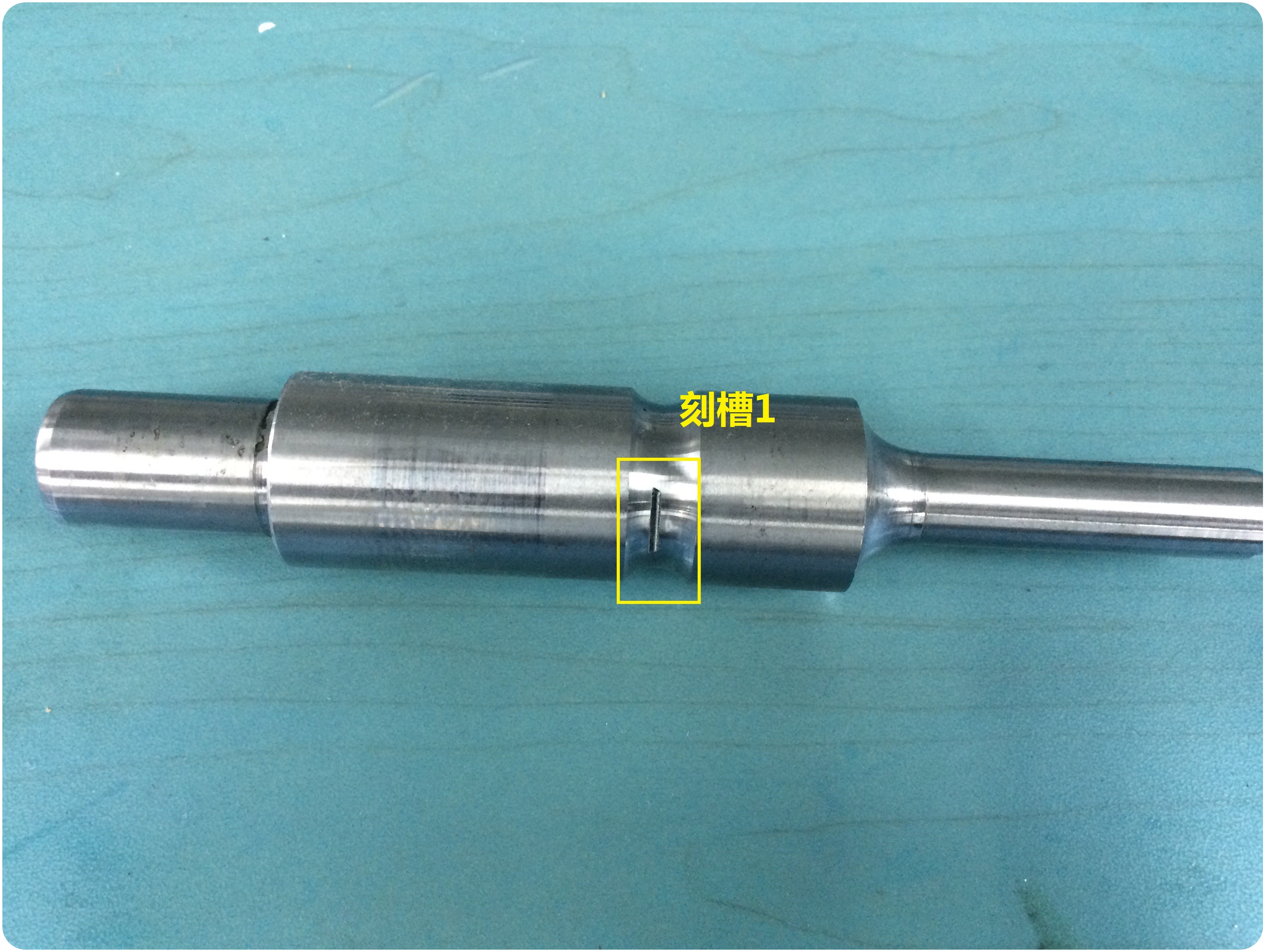
Figure 1-2 Artificial groove 1 (1mm) on the rotor shaft
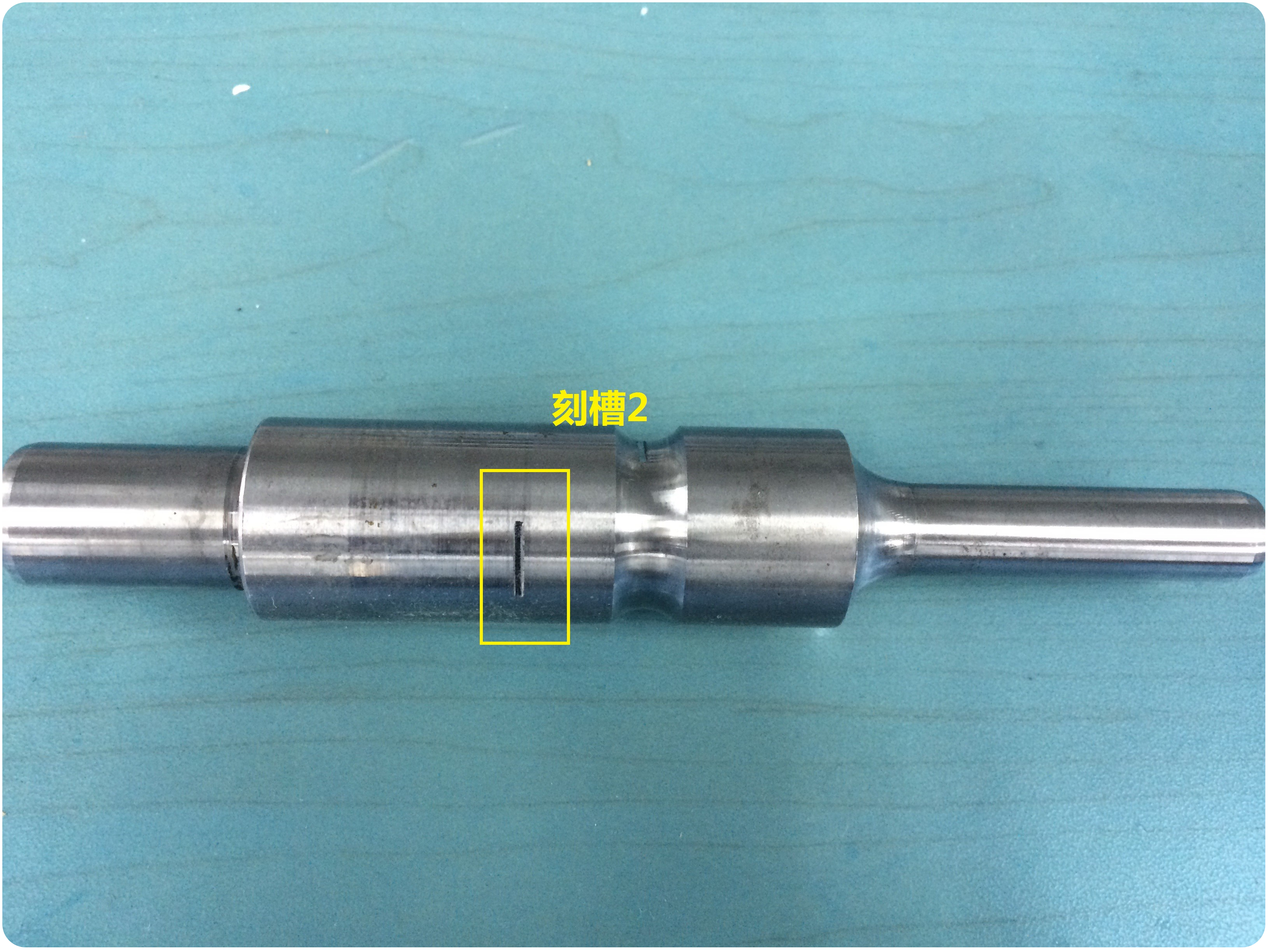
Figure 1-3 Artificial groove 2 (1mm) on the rotor shaft
2. Selection of Instrument, Probe and Wedge
(1) Instrument: Doppler PHASCAN phased array ultrasonic detector. All phased array equipment models of Doppler can meet the inspection requirements.
(2) Probe: Doppler 7.5S16-0.5×10 cobra phased array probe.
Wedge:
1) SD10-N60S (AOD 21.34°)
2) SD10-N60S (AOD 26.67°)
3. Inspection Method
The Doppler 7.5S16-0.5×10 cobra phased array probe matched with AOD 21.34° and AOD 26.67° wedges is proposed to conduct circumferential phased array ultrasonic testing on the shaft from the Φ18 mm end and Φ25 mm end respectively.
(1)Inspection at the Φ18 mm End:
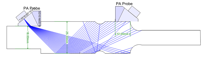
Figure 2-1 Schematic diagram of probe arrangement at Φ18 mm end
(2)Inspection at the Φ25 mm End:
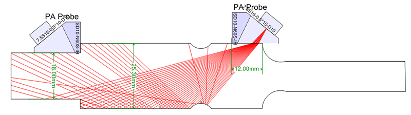
Figure 2-2 Schematic diagram of probe placement at the Φ25 mm end
4. Inspection Results
(1) Schematic diagram of actual probe placement at the Φ18 mm end
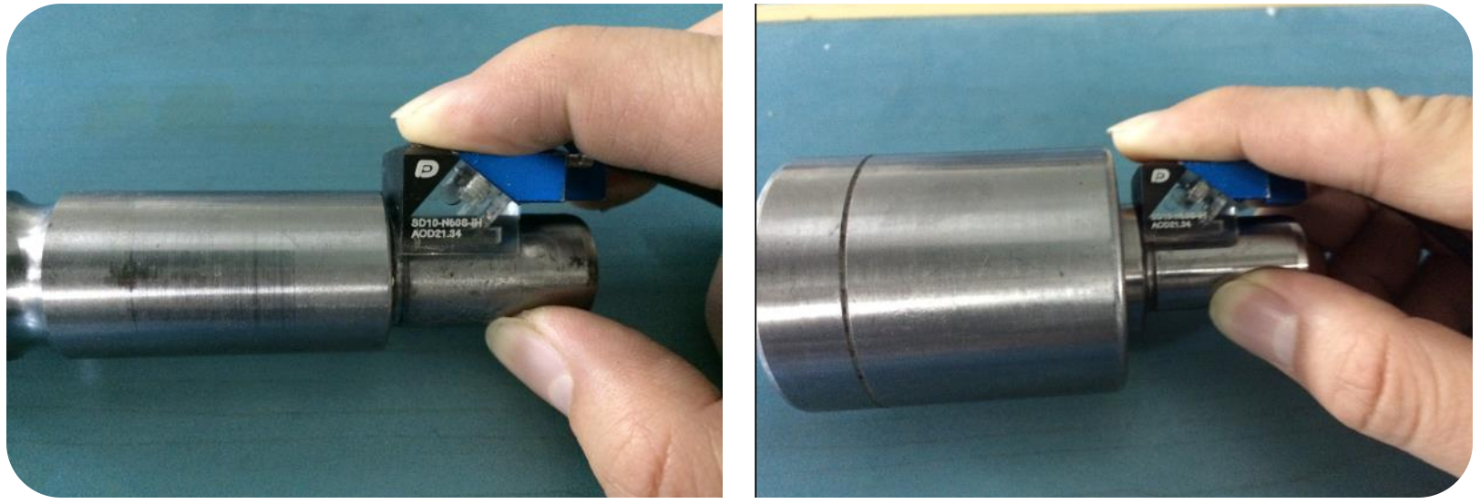
(2) Schematic diagram of actual probe placement at the Φ25 mm end
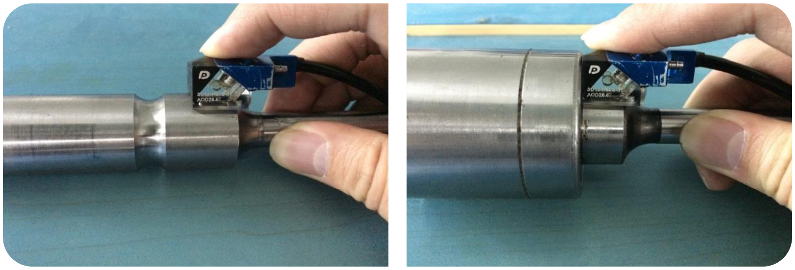
(3) Inspection result of No.1 artificial groove at the Φ18 mm end
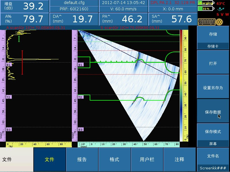
(4) Inspection result of No.2 artificial groove at the Φ18 mm end
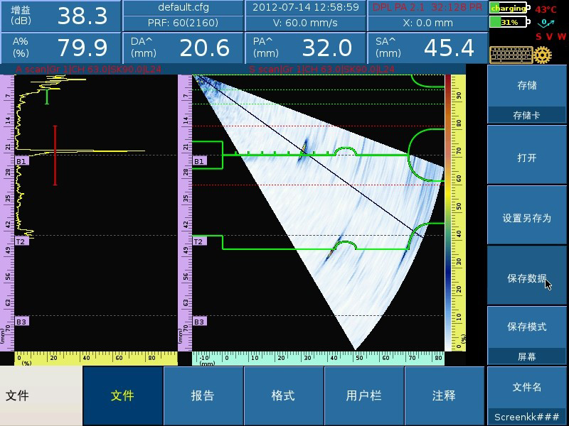
(5) Inspection result of No.1 artificial groove at the Φ25 mm end
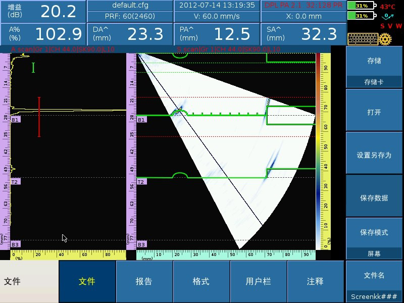
(6) Inspection result of No.2 artificial groove at the Φ25 mm end
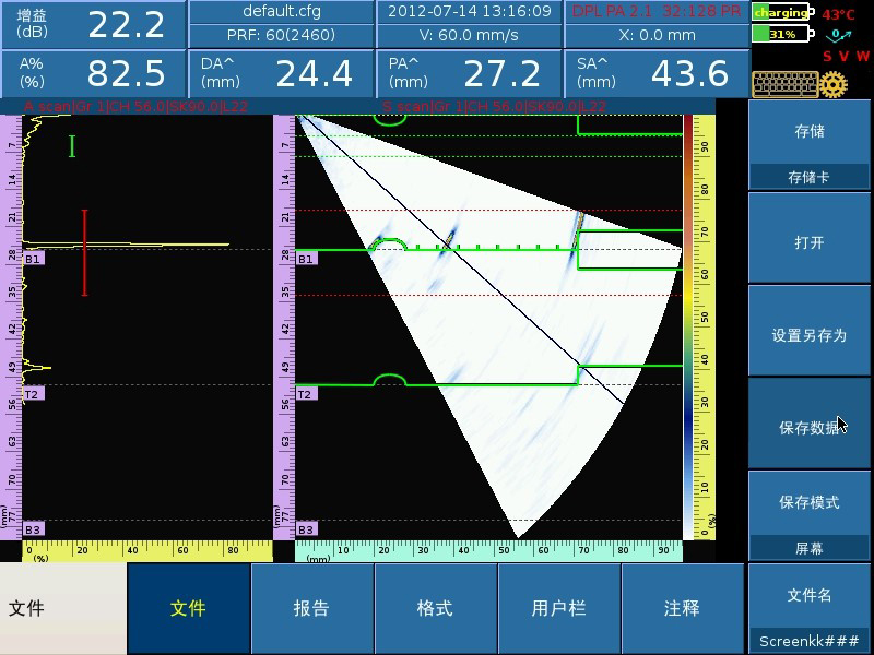
It can be concluded from the test results that phased array testing delivers high efficiency and rapid detection for workpieces with complex structures and numerous fixed echo signals. The advanced AutoCAD import function of the equipment can be fully utilized to assist in the identification and analysis of workpiece defects.