Stock Code
301528

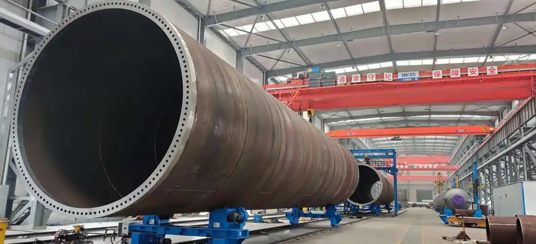
Throughout the entire service life cycle of wind turbines, the tower, as the primary load-bearing component, is continuously subjected to alternating loads during long-term operation. The excellent fatigue resistance of bolts connecting various turbine components serves as a critical guarantee to prevent severe tower and unit damage, and even tower collapse accidents.
During operation, bolts operate in harsh working environments and under complex stress conditions. With the increase of service years, loosening and crack defects are highly prone to occur. Once such defects develop to a certain extent, they will seriously threaten the operational safety of wind turbines. Given that the reliability of bolt connections directly determines the overall performance and service life of the units, regular inspection for bolt defects is essential. Early detection of cracks enables timely replacement and maintenance, so as to eliminate potential safety hazards.
Meanwhile, the service life of early-installed wind turbines in China is gradually expiring. It is necessary to evaluate their structural health status for current operation and life extension periods. As key load-bearing structural parts, the health condition of bolts is also a vital part of wind turbine life extension assessment.
I. Common Nondestructive Testing Methods
At present, the commonly used nondestructive testing methods for tower bolts of in-service wind turbines in the wind power industry are as follows:
1. Magnetic Particle Testing (MT)
It is a nondestructive testing method that detects surface and near-surface defects of ferromagnetic materials by the accumulation of magnetic particles in the leakage magnetic field around defects. Workpieces made of ferromagnetic materials such as steel and iron are magnetized. Leakage magnetic flux generated at defective areas attracts magnetic particles. The distribution of magnetic particles visually reveals surface and near-surface defects of the tested components.
2. Ultrasonic Testing (UT)
Ultrasonic waves generated by a sound source are transmitted into the workpiece in a controlled manner. During propagation inside the workpiece, the ultrasonic waves interact with the material structure and internal defects, leading to changes in propagation direction or signal characteristics. The reflected or transmitted ultrasonic signals are captured by testing equipment for subsequent processing and analysis. Based on the characteristics of the received ultrasonic waves, the existence, location and morphology of internal and surface defects in the workpiece can be accurately evaluated.
3. Ultrasonic Phased Array Testing
This method shares a similar working principle with conventional ultrasonic testing, both based on the pulse reflection theory. Compared with conventional ultrasonic inspection, it offers the following advantages:
(1) Ultrasonic phased array technology deflects ultrasonic beams by sequentially exciting each element of the probe to perform angled scanning. When inspecting welds, it eliminates the need for zigzag scanning; only linear movement along the weld is required. For forgings, it provides a wider scanning coverage and higher inspection efficiency. Meanwhile, it effectively reduces missed detections and improves inspection accuracy and reliability.
(2) Sequential excitation of phased array probe elements enables ultrasonic beam focusing, which is generally unavailable in conventional ultrasonic testing (except with focused probes). This overcomes interference caused by the ultrasonic near-field zone and allows effective inspection of thin-walled workpieces.
(3) Phased array testing supports B-scan, S-scan and C-scan imaging, presenting defects in an intuitive and clear manner. Defects can be identified through color differences in multi-mode imaging, facilitating accurate quantitative evaluation of internal defect equivalents. In contrast, conventional ultrasonic testing can only judge defect sizes based on echo amplitude.
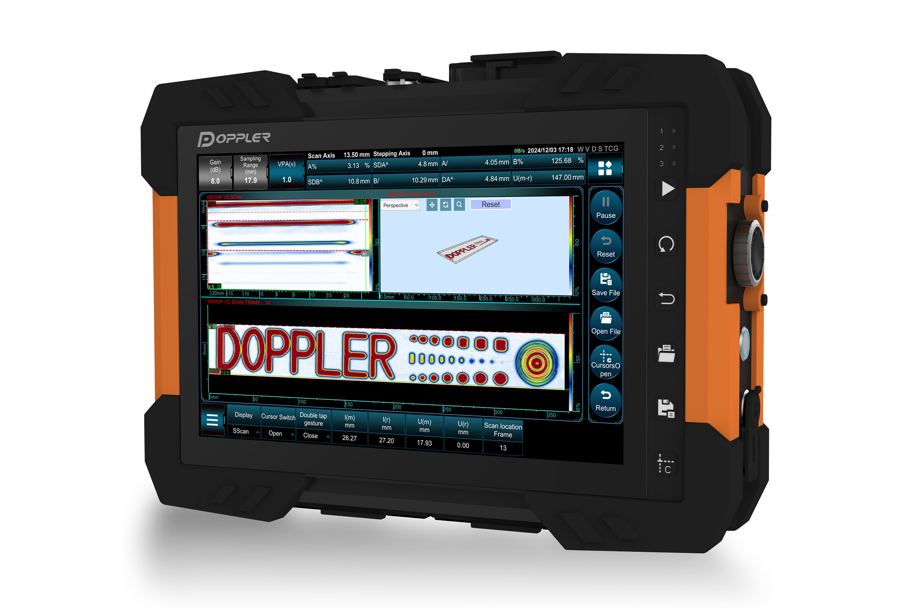
Doppler NovaScan V3 Portable TFM Phased Array Ultrasonic Detector
II. Non-Destructive Testing of Bolts
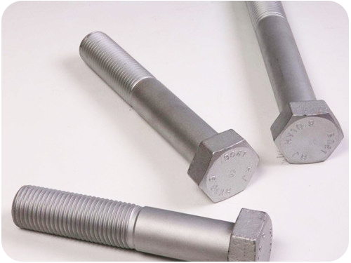
High-strength bolts are a type of rigid bolt without holes. Their crack wave features are clear, steep and sharp in waveform, and cracks generally occur at 1 to 2 thread pitches near the joint surface. For relatively large cracks, the bottom echo is significantly weakened or even completely lost. Meanwhile, the thread echoes immediately following the crack echo will be attenuated or disappear due to shielding by the crack.
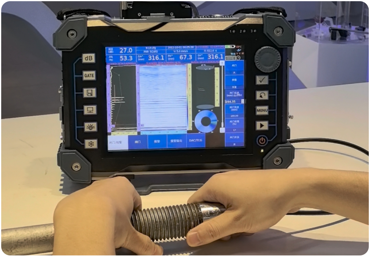
Phased Array Ultrasonic Testing Solution
Common phased array ultrasonic testing methods for bolts include linear scanning (for perforated blade bolts), sector scanning (for standard bolts with flat end faces), as well as total focusing method (TFM) for small bolts and 3D total focusing method.
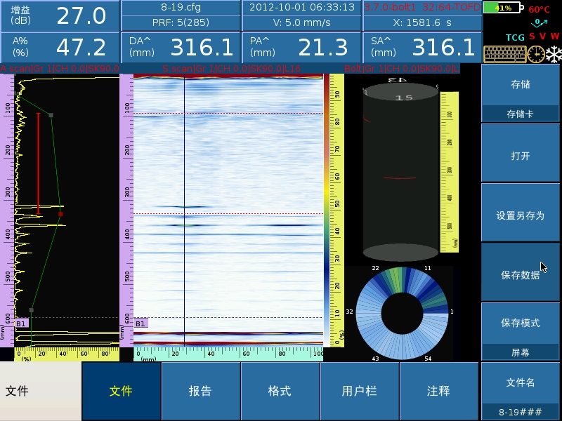
FlexScan – Linear Scanning Inspection Result
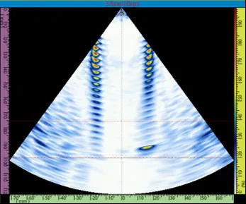
FlexScan – Sector Scanning Inspection Result
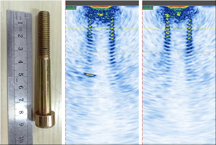
NovaScan – TFM Inspection Result
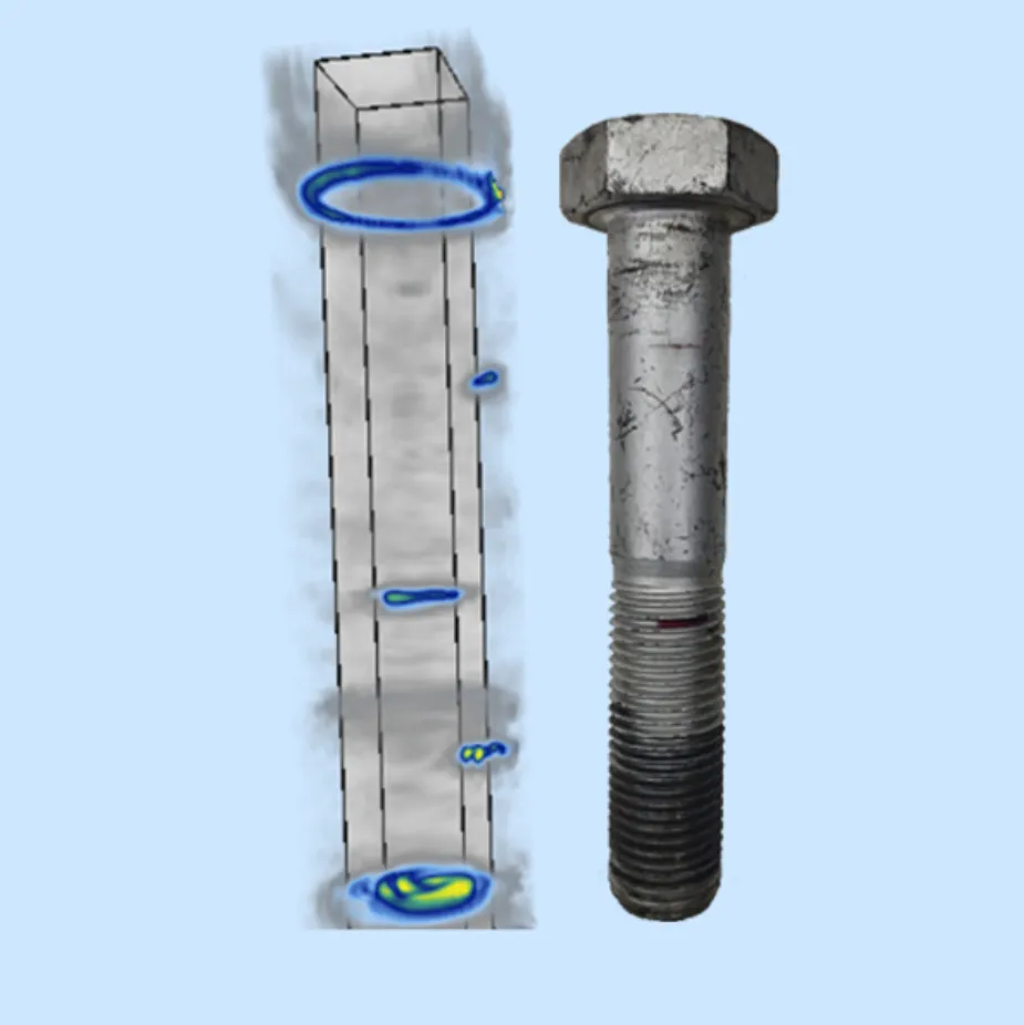
NovaScan – 3D TFM Inspection Result
Summary
With the increasing service life of wind turbine units, the risk of fatigue damage to load-bearing structural bolts continues to rise. Meanwhile, the wind turbines installed and put into operation in the early stage in China are approaching the later stage of their design service life. Life extension evaluation is required to determine their continuous service feasibility. Therefore, non-destructive testing of bolts is of critical importance.