Stock Code
301528

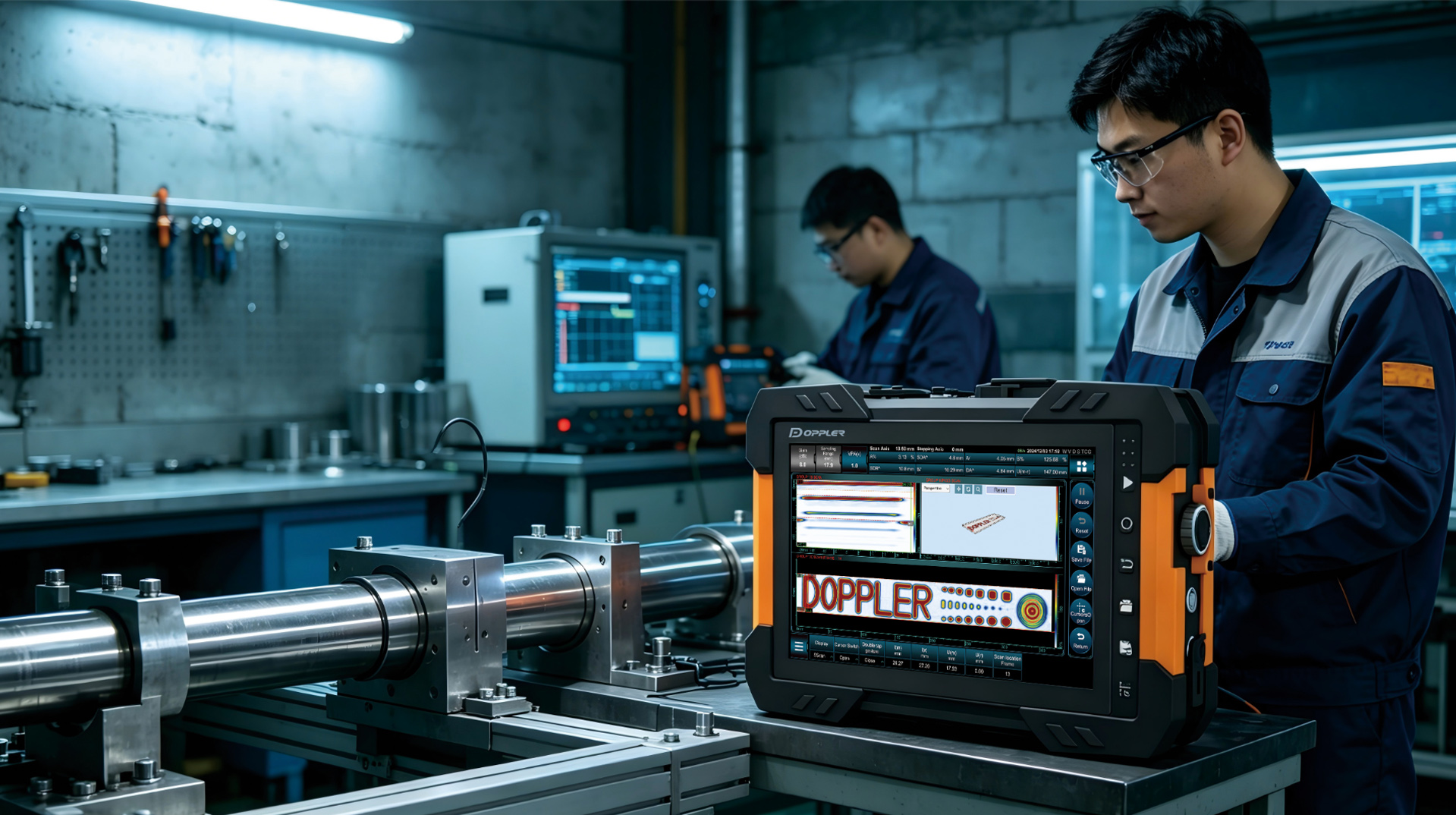
I believe most of you have a basic understanding of the excitation voltage of phased array systems. Whether it is conventional ultrasonic testing or phased array ultrasonic testing, voltage excitation works much like striking a drum with a drumstick. The harder you hit, the louder the sound and the stronger the penetration. Therefore, equipment with a high excitation voltage is essential for inspecting highly attenuative materials such as stainless steel and austenitic steel, as well as for applications requiring long sound paths, e.g., heavy-wall castings and forgings.

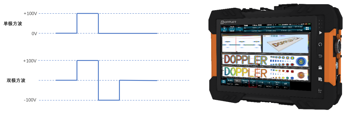
Bipolar square wave
Most modern phased array devices adopt square wave excitation, which is divided into unipolar square wave and bipolar square wave, as shown in the figure below. The effective voltage generated by bipolar square wave excitation is twice that of unipolar square wave excitation. Therefore, with the same supply voltage, bipolar square wave excitation delivers higher excitation energy, enabling the inspection of more challenging workpieces.
Effective output impedance
When it comes to voltage, there is another important concept that is often overlooked: effective output impedance. Simply put, it refers to the internal resistance of the instrument, while the probe acts as an external load resistance connected to the instrument.
Intuitively, most people believe that the lower the output impedance, the stronger the load driving capability. This holds true for DC or low-frequency circuits such as audio power amplifiers. However, the situation is entirely different for high-frequency, pulsed and broadband ultrasonic phased array systems. The core objectives of such systems are to maximize power transmission and ensure optimal waveform fidelity, rather than simply enhancing driving capability.
According to the Maximum Power Transfer Theorem, maximum power is delivered to the load when the output impedance of the source is equal to the input impedance of the load (conjugate matching). This allows the rated maximum voltage to function to its full potential.
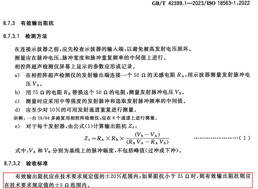
This requirement is clearly specified in GB/T 42399.1-2023 (equivalent to ISO 18563-1:2022), which stipulates that the effective output impedance shall be within ±20% of the value specified in the technical requirements.
Influence of Voltage Value on Inspection
Now that we've gone over the factors influencing the excitation voltage of phased array systems, let's look at how voltage affects inspection performance in practical applications with a concrete example.
The following shows the test results of a highly attenuative material. At an excitation voltage of 50 V, the amplitude of the backwall signal is approximately 89.98%, the ambient noise level is about 24.81%, and the signal-to-noise ratio (SNR) is roughly 11.2 dB.
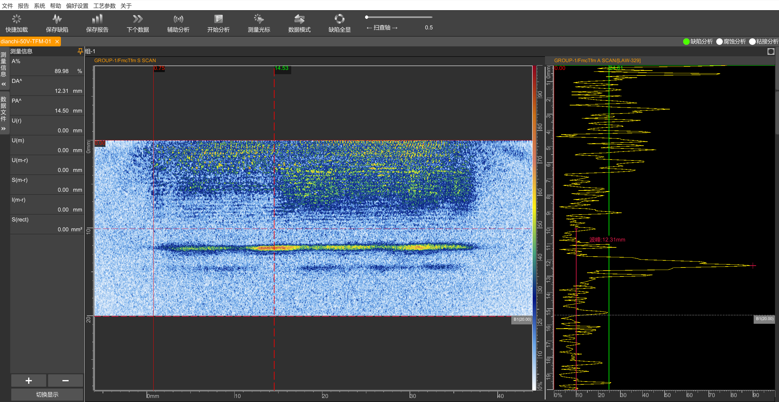
When excited at 160 V, the inspection results are as follows: the backwall signal amplitude is approximately 89.98%, the ambient noise level is about 9.28%, and the signal-to-noise ratio (SNR) reaches around 19.7 dB.
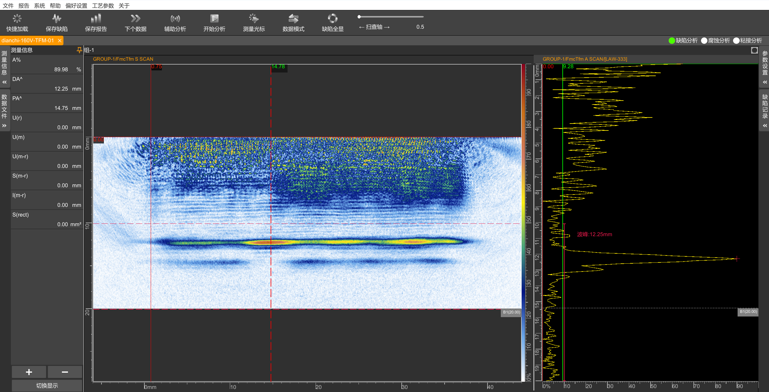
It can be seen from the above test results that a voltage difference of 110 V leads to an 8.5 dB difference in signal-to-noise ratio. This demonstrates that excitation voltage has a significant impact on the signal-to-noise ratio during the inspection of highly attenuative materials.